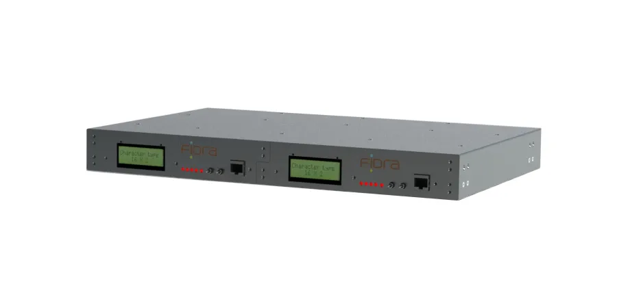
The Fidra is a fiber-optic switch designed to monitor, reroute, repeat, boost and disable up to 3 fiber optic communication pairs. Utilizing industry standard SFP modules allows Fidra to support various optical communications including single/multimode, LED/Laser as well as multiple wavelengths. Common applications for Fidra include:
The Fidra was designed for applications such as protective relaying and other environments where substation hardened equipment is required. It resides in line with equipment utilizing fiber optic communications. It allows for testing and maintenance without the need to remove and reroute fiber cables, eliminating costly fiber damage and ruining components caused by improper handling.
The Fidra is programmable to route any receive signal to any of the three transmitters. All routing is performed at the physical layer (PHY layer), therefore, Fidra communications are transparent regardless of the brand of communications equipment used. No protocol support is required and only microseconds of delay are added to the signal propagation time, making it ideal for differential relaying applications. Testing and monitoring are streamlined while providing safety to the technician and ease of implementation to the system.
System configuration is performed via the built in web server, which allows configuration of the 3 basic modes of operation Normal Mode and two Test Modes. These two modes eliminate the need to reprogram the unit for routine maintenance and testing of the connected devices. The mode is controlled by switches on the front panel. A Cutout switch input is also provided to disable all transmitters quickly and easily.
The SFP can be singlemode or multimode. Data rates up to 155 Mbps are supported. A single Fidra can have singlemode, multimode, and/or different frequency heads simultaneously. Since the SFP module is not soldered to the board, they are easily added or changed in the field.
Monitoring of fiber optic signals is standard. The Fidra displays the level of the three receivers on the front panel. Alarming for a drop in signal level, receive fail, transmitter failure, power supply failure, and test mode function are all included.
The Fidra is programmed using a web browser. A PC can be connected to the unit using a standard Ethernet cable. A web server is embedded in the Fidra and can be accessed one of three ways.
The Fidra supports Dynamic Host Configuration Protocol (DHCP). When enabled, the Fidra's DHCP Server assigns an IP address to the PC. This allows the PC to be connected directly to the Fidra, making field connections more straight forward. Using the DHCP server also allows the Fidra not to be permanently connected to the sub-station's Ethernet network.
The Fidra may be set-up as a DHCP client or it may be assigned a fixed IP address.
The fiber port settings map is easily set using radio buttons. The three transmitters can set to any of the three receivers. This allows straight, local loopback, remote loopback, and bypass logic to be programmed in Normal mode, Test mode 1 and Test mode 2. The mode being utilized is controlled by locking toggle switches on the front panel.
Alarms may be disabled or bypassed in Test mode using the programming menu.
A unique feature is the RX Drop alarm. This alarm allows the user to program a receive level in dBm at which the Fidra will indicate an individual receiver has fallen to or below this setting. This is a preemptive warning of decreasing power and indicates a drop in level before the attached IED fails to receive the signal.


Our expert support staff and engineers are available to help provide a quote or answer to any questions.
Request a quote