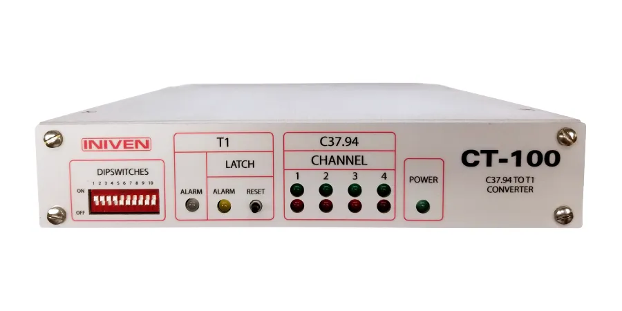
The CT-100 converts and combines up to four IEEE Std C37.94 fiber optic interfaces into a single T1 electrical interface. The CT-100 is designed to multiplex up to 4 C37.94 channels without the need to program or map the channels in the T1 frame. The physical ports on the CT-100 directly correspond with the I/O’s on both ends of the T1 channel. A C37.94 channel connected to port 1 of the CT-100 will be mapped to port 1 of the corresponding CT-100 on the remote end of the T1 channel. The CT-100 is designed to communicate point to point over a third party electrical T1 channel, such as a leased T1 channel from a phone company. The master clock will be sourced from the T1 channel and the CT-100 will act transparently in the communications path.
A single CT-100 aluminum enclosure is 1U tall and half the width of a standard 19”rack. It can be mounted alone in a 19” rack, using extended brackets, side by side, with standard brackets, or the unit can be shelf mounted. Other Iniven products that use the same enclosure type can be mounted side by side with the CT-100 in a single 1U 19” rack.
The rear panel contains all the I/O connections. Communications interfaces consist of one RJ 45/48 T1 plug and up to four C37.94 fiber optic interfaces. Each C37.94 interface has one transmit and one receive 850nm multimode head with an ST connector. A singlemode 1310nm LED C37.94 interface is available as an option. The CT-100 is equipped with either two or four C37.94 channels.
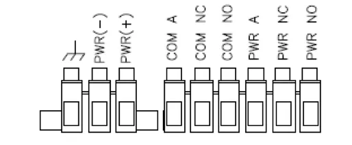
Two sets of removable terminal blocks, for wiring power and alarms, are located on the rear of the chassis. Each connection is labeled as indicated in the drawing below:

The CT-100 uses a wide range power supply capable of operating on a DC voltage between 24 and 125V. One of the two terminal blocks are dedicated for DC connections. The connections are for +, -, and ground.
The second terminal block is used to connect the two, dry contact, Form C relay alarms. The alarms are for communication fail on any of the communication channels, T1 and/or C37.94, and power fail. Each alarm has 3 connections, normally open (NO), normally closed (NC), and armature (A). This allows the user to select the type of output they would prefer without the need to perform any programming or jumper settings. The user simply connects the armature and their choice of NO or NC. The alarm relays do not have polarity and accept voltages up to 125VDC.
There are two status relay alarms on the CT-100: Power Fail and Com Fail. Each alarm relay is a Form C relay and may be used as NO or NC.
Power Fail is used to indicate that the unit’s power supply can no longer operate within acceptable parameters. In the case of a power failure, all status relays will return to their “normal” position and the green Power LED on the front panel will turn off. When power is being supplied to the unit, the green Power LED will remain illuminated.
Com Fail is a common alarm shared by the, up to, four C37.94 interfaces and the T1 interface. If any of the communication channels were to stop communicating, the Com Fail relay will go to its “normal” state. This alarm will also return to normal if there is a power failure.
The front panel contains 8 C37.94 LEDs, two for each channel. A green LED indicates communication is detected over the channel. A red LED indicates that the channel is on but no communication is detected. If neither LED is on, the channel has been turned off by the DIP switch on the front of the CT-100.
There are 2 T1 Fail indicators and a reset switch located on the front panel. If a loss of communications is detected on the T1 channel, the T1 ALARM multi-colored LED on the front panel will turn red. The sensitivity of the loss of communications (T1) is set by switch 5 on the front panel DIP switch. The setting is either high or low. The front panel has a T1 LED. When the ALARM LED is green, the T1 channel is communicating properly.
When a T1 loss of communication alarm is detected, the amber LATCH alarm will illuminate. This LED will remain lit until an operator presses the RESET button. Once the latch is reset, it will remain off until another loss of communication alarm is detected.
The front panel has a 10 position DIP switch. Switch 1 through 4 operate as follows:
The other switches are not used at this time and are reserved for future use.
Our expert support staff and engineers are available to help provide a quote or answer to any questions.
Request a quote